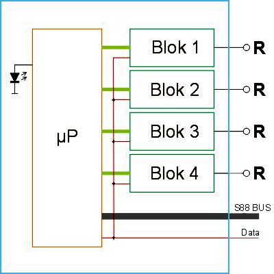
The control board for the blocks
Basic functions:
- Block current measurement for occupancy detection to determined the location of each train, regardless of the decoder type (old or new), lamps or LEDs.
- Short circuit detection per block which in the case of a short circuit switches off only that block.
- Occupancy information and short circuit reporting by a built-in "S88 function" passed to the program.
- Each block has stabilized track voltage causing a steady speed to be achieved even with old motors and old decoders
- Control board has 4 boosters, each of which can make just about 3A and cause even with prolonged shorting no warming.
- The card can be put into different modes for <regular drive> or <initial phase (Delta mode)> and listens to address 80 for this.
- A microcontroller does the job and a LED indicates the status of the card: Green = normal driving, Green flashing = boot phase and red = block in short circuit
.
basic card diagram
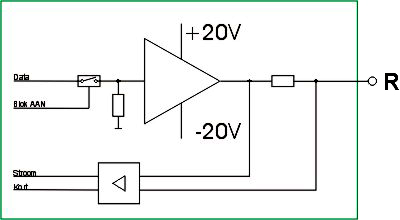
The individual booster
This includes a power switch (3A) with analog current limit and a stabilized output for stable driving.
Each block can be individually turned on and off by the processor if no data is present or if a short circuit occurs.
Hence, no large cooling surfaces needed.
Feedback
The Feedback of both shorts and consumption will be done by the microcontroller in S88 format.
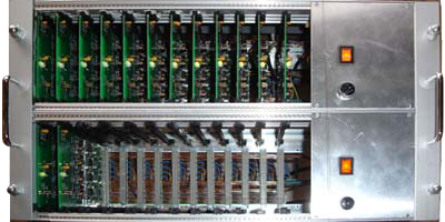
practical realization
For the layout of the train table just under 100 blocks were needed, and was chosen for a 19" rack with 2 x 12 cards x 4 blocks = 96 blocks.
Each sub rack has its own power supply 300VA roughly 22V unstabilized supplies, good for 18V stabilized driving voltage.